Long story short – started with 5.8GHz on mini FPV copter (pocket rocket quad), soon got another, tried 1.2GHz (see earlier videos here) and finally picked 2.4GHz for my video.
Things change with time, Lithuania now has #1 Wi-Fi coverage/speed in the world and now i found that 2.4GHz for video usually has lower range than old 5.8GHz setup. It still works fine in forests or far far away from populated places, but flying in city is next to impossible (for example, Vilnius Old Town, near Užupio Kūdrų parkas – loosing video in 20m away from me, using 2370MHz or 2510MHz which should be away from common Wi-Fi range).
5.8GHz has too low penetration, few trees – and you are flying blind. 1.2GHz – good penetration, but there’s another issue – antennas… They are huge, compared to 5.8GHz…
Let’s try to do something about it. Few draft models in CST, few cuts from material i have around and….
- All antennas for my comparison:
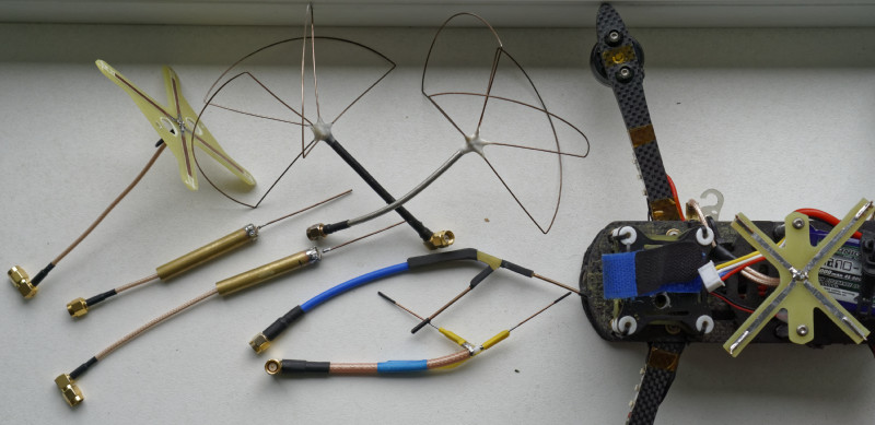
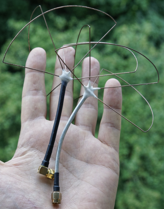
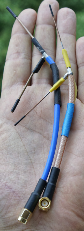
- My old, but good working cloverleaf antennas (VSWR < 1.3 for both)
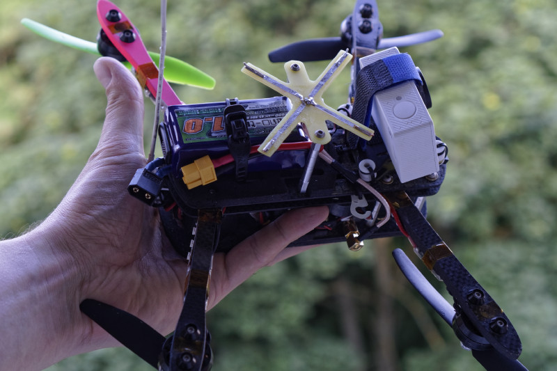
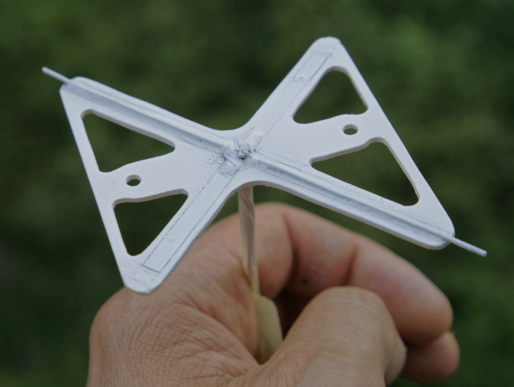
- Flat-v2 mounted on copter
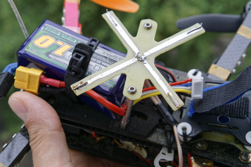
- Flat-v2 mounted – close up
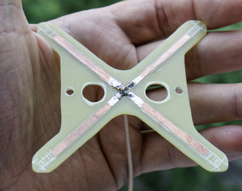
- Flat-v1 (or “crossed dipole with phase delay on coax) – bottom view
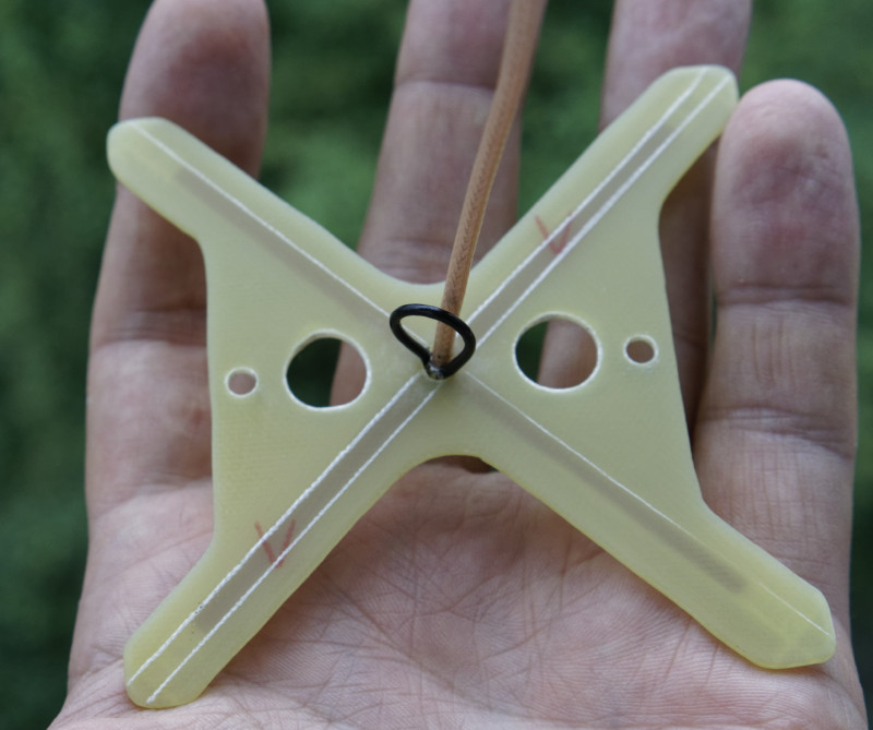
- Flat-v1 – top view
- Dipoles
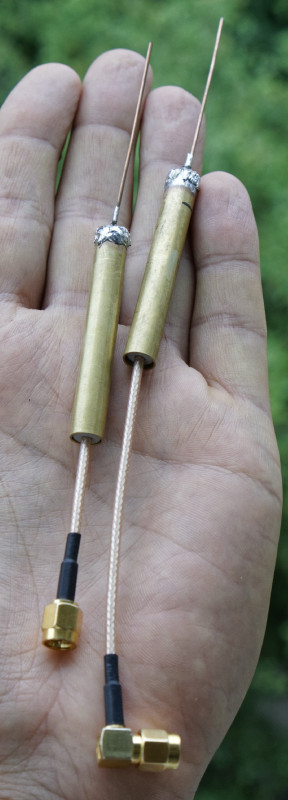
- Vee antennas (again, tested to be VSWR < 1.3 for both)
My requirements:
- antenna should be near indestructible (well, concrete, asphalt and rocks do their job anyway, but should survive common crashes in fields/trees and so on)
- omnidirectional as possible (usually i fly everywhere around me)
- minimized effects from multipathing (obstacles everywhere!)
- minimum space on copter (it’s still “mini”)
- should work without issues +/-45° in any direction from “hover” position
- as simple as possible, so you can make them at home without special tools
So, looks like linear antennas are out of question – no multipath rejection, also lots of losses from polarisation change on tilt/roll. But i tested them anyways – nothing new, they do not perform well.
What’s left – circular polarisation. Cloverleafs are cool, but they are huge – i will hang on every branch. Also, they aren’t stiff – do not want to fix them after every crash, so i need something better. So, i come up with two “flat-type” antennas. Both are identical from technical point of view – both are “crossed dipoles”, just different phase-delay method.
Conclusions from my testing:
- Linear polarisation is useless on mini – multipathing hurts, FFF and banking added polarisation losses kills link
- CP – cloverleaf performs best, but it’s too fragile and too big
- flat-v2 is slightly worse (or at the same level) as cloverleaf, but it’s tiny
- flat-v1 is slightly worse than flat-v2, but that’s probably due to manufacturing mistakes, should be at approx the same level
So, in short (note – all antennas are tuned for 1280MHz):
Flat v1:
- Crossed dipoles with delay line. No balun, no matching line (not everyone has thin 75Ω cable at home), so do not expect something better than 2.0 VSWR (in fact, should be around 2.5 if made only with dimensions – still more than enough for our needs).
- Pros:
- Very easy to do (even knife-cuts are straight lines between dipole sides, so 4 long cuts with knife and…)
- Easy to tune even without any special tools (using RSSI, current method or just plain image quality) – tune each dipole, then join them and you are done
- more space for manufacturing tolerances, compared to v2
- Cons:
- Slightly worse image quality, compared to v2
- phasing line is not so easy to solder
- requires thin coax OR making huge holes in middle of plate
- no space for coax balun, at least 2mm+ (thin coax is probably OK, but not sure if this would be effective), so – you will live with unmatched antenna… Still fine for flying
Construction is very simple – you can download templates here:
flat_v1 – Solidworks part/drawing (holes are adjusted to Pocket Rocket top mounting – 48.5mm, you probably want to adjust them to your copter)
flat_v1 – PDF drawing, for printing. Have in mind, that this drawing is oversized – arms can be much shorter.
Print, glue them to PCB, cut with fret saw, drill holes. Then take knife and something straight and stiff (metal ruler preffered) and cut tracks on top. Peel not needed copper with pliers and knife, done.
- If you want to tune it (using any method) – solder only one dipole to coax (opposite tracks). Trim dipole ends in 1mm increments until you get best VSWR (~1.7 without matching lines)/RSSI/current. Do the same with another dipole. Only then solder phase delay line (see picture above – you will clearly see trim cuts).
- If you just want “stuff that should work” – cut each track to 42mm. Have in mind, that not every PCB is identical, so with different material this may be way off…
You can see “shortened tracks” on antenna pictures above.
Now pick piece of coaxial cable, cut it to 48mm (you can calculate proper length if you know your cable velocity factor – 58.5*Vf – in millimeters) and solder it in parallel to any dipole. Solder another end to another dipole.
Connections should be (pictures not mine):
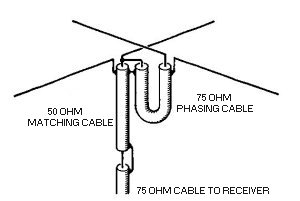
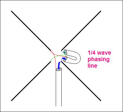
Things to look for:
- track width isn’t critical, but try to keep it around 2.8mm
- PCB around can be in any form, but keep at least ~3mm from copper, or you will need to re-tune antenna
- you can solder wires on top of tracks – for better bandwith and more stiffness, but this increases weight
- you want to keep sides of copper tracks as smooth as possible. This is what matters – radiation coming from “sides” of tracks, so if you have “tooths” here – actual radiating length is longer and you will have detuned antenna
Mount it on copter and go flying ;-)
Flat v2:
- Crossed dipoles with phasing done by different lengths of wire. Also known as turnstile (IBCrazy named own “crosshair” but “turnstile” was there for ages already). Easy to add coax balun (but won’t get much from it), VSWR without matching elements should be ~2.0-2.5 (which is enough for indestructible multicopter antenna).
- Pros:
- Very simple construction – coax + PCB, no complex soldering and so on
- takes less space compared to v1
- can hold branches better than v1 – v1 has hanging coax loop from bottom, in some (rare, i guess) situations this may be aditional point of failure
- easy to solder balun if want to tune it further
- Cons:
- not easy to tune – you need VNA to properly tune such antenna (or, maybe – you can cut tracks (make 4 sections), tune longer arms as dipole, then re-calculate shorter ends to 0.84 of longer length – untested) – so make it precisely or just go v1
- slightly less bandwith compared to v1, but this should be not noticeable for 99% of fly time
Construction:
flat_v2 – Solidworks part/drawing (holes are adjusted to Pocket Rocket top mounting – 48.5mm, you probably want to adjust them to your copter)
flat_v2 – PDF drawing, for printing.
Print, glue them to PCB, cut with fret saw, drill holes. Then take knife and something straight and stiff (metal ruler preffered) and cut tracks on top. Peel copper from sides with pliers and knife. Sand sharp edges, try to keep tracks edges smooth and straight.
Things to look for:
- track width isn’t critical, but try to keep it around 2.8mm
- PCB around can be in any form, but keep at least ~3mm from copper, or you will need to re-tune antenna
- you can solder wires on top of tracks – for better bandwith and more stiffness, but this increases weight. If you sanded tracks too much – you can extend them with wires (pdf drawing is 100% of size), see my pictures (those upward-bent wires also work for another purpose, but you can live without them)
- you want to keep sides of copper tracks as smooth as possible. This is what matters – radiation coming from “sides” of tracks, so if you have “tooths” here – actual radiating length is longer and you will have detuned antenna. Better keep narrow tracks, but not “saw tooths” on edges
- short arm compared to long arm should come to 0.84 ratio, no more and no less
Solder coax shield to one “long-short arm” pair, center wire – to another.
Video with all antennas (see markings in video) – i tried to fly the same route, but it’s not easy….
Two different cams in video (Effio-V in beginning, Nexchip 2040 in fields). My DVR is very picky on noise – it simply duplicates frames on sync loss, so even small noise looks “unflyable”. Actually, it’s much better on HMD/goggles. Not best video i can do, but do not have anything better available at this moment.
First part – linear vs circular (matching antenna – linear or circular on HMD); second part – comparison between cloverleaf/flat v1/flat v2 antennas (another cloverleaf on HMD all time).
Further improvements:
- inclined arm turnstile – much, much better matching (can archieve 1.2 VSWR if done properly), but it requires “3D” elements, sticking out of PCB. This makes it vulnerable to crashes
- 1/4λ coax balun – very easy to make and it could improve antenna… Slightly. Just cut 58.5mm coax, clean up shield ~1mm from both ends (do not touch middle wire), solder to “main coax” shield on top. Then uncover some shield on “main coax” where balun coax ends and solder them both. Pic (not mine):
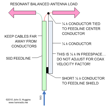
(note – frequent mistake – middle wire on balun coax is not connected to anything) - tube balun (with ~0.23λ split) is even more effective, but this probably will limit mounting options (rigid tube sticking from bottom of antenna – fail for minicopter)
- probably both antennas can be done by PCB fabs, so they may be precise and better tuned. Even more, i think that both antennas can be 3D-printed (with wire-tracks), so yet another possibility (but do not forget to re-calculate everything for different Vf)
- Should be easy to make them for 2.4GHz, but for 5.8GHz – there are many better options.
And to repeat – do not expect them to be “perfect antennas for range flying”. Those antennas will radiate lots of power back to VTX. Those antennas won’t have circular polarisation – it’s elliptical in best case, with distorted radiation pattern.
But they will work very well on minicopter – where mounting space is limited, crashes are frequent and nobody cares about 50km+ flights.
Update #1: had lots of crashes, ( > 40 broken props, 2x broken arms on PR, 2x broken Xiaomi Yi cases, killed SunnySky X2204 motor and so on) – but antenna is like new. No signs of wear, no difference in performance. I’m very happy with this “indestructible” antenna (using v2 ATM) so far,
Update #2: omni antennas on both ends (flat v2 on copter), abandoned factory, lots of steel and concrete, more than 200m from PF and turning around:
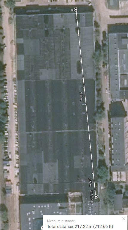
Flyable without serious issues, except when i line up with outer wall – no way to penetrate 200m of concrete =) Anyway, returned back safely…
See gif’s with that flight (forward and back):
https://plus.google.com/+AndriusNarbutas/posts/3zvH4L8jkQF
https://plus.google.com/+AndriusNarbutas/posts/Zka3bpz8sq9
Update #3: after many crashes antenna started to show signs of wear. 12mm width, 1.6mm thickness glass fiber can’t handle many “landings”. It’s still working, but… I had many ideas to incorporate, so there’s “flat v3”:
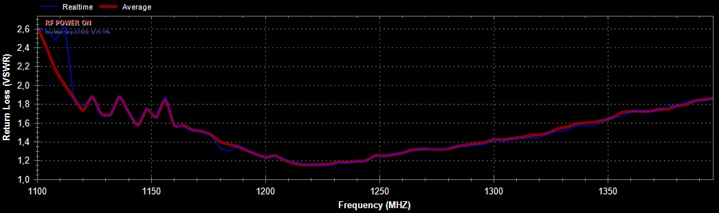
(painted with Hammerite paint, shifted frequency down by ~10MHz, not big deal, but can hold longer).
Arm dimensions – short: 32mm, long (including wire): 54mm. Wire thickness is not important, also everything can be done on PCB (but would be slightly too big for my multi and i would need to re-make battery mount).
As you can see – much, much better SWR compared to earlier versions. Will try “factory penetration mode” again =)
Next step – “variable length quadrature feed” design – again, similar “square-cross” design, but every arm will have different length. This should (in theory at least) help to archieve perfect radiation pattern while keeping very good VSWR and axial ratio. Also, few ideas how to improve stiffness without increasing weight. Lots of testing ahead…