I had several RF heads – based on AD8317 (and working from PC), also based on AD8313 (you can get entire RF head assembled for ~20$ or so at https://www.sv1afn.com/projects.html) and decided that i need portable box for measuring signal levels and VTX power.
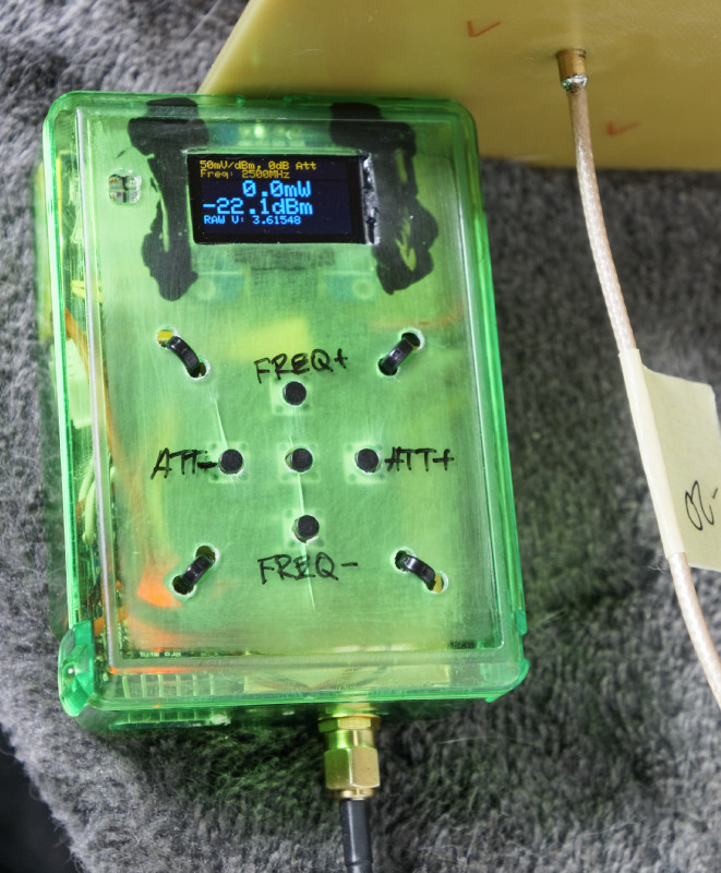
Did that, working well:
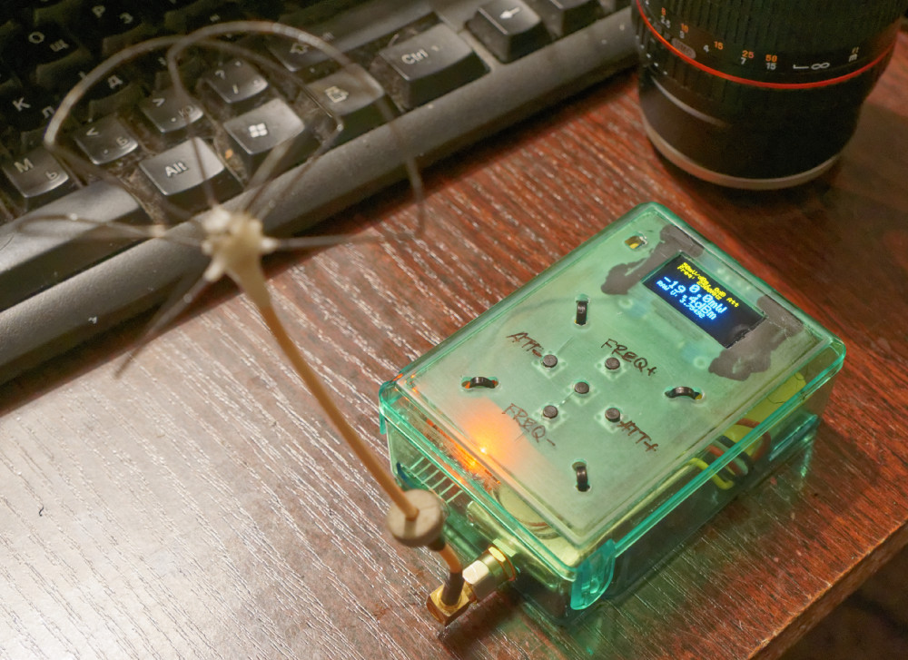
it’s actually very simple and entire box costs ~35$ or so (if you have basic parts and attenuators already). Accuracy is acceptable (+/- 1.5dBm in -10 … -40dBm range).
And no, it won’t work better than other tools (even RF explorer is much better with it’s -105dB+ range); it won’t do correct math for frequency (MCU is too weak to do proper calculations). So, if you need serious tool – go look for other solutions. If you need something cheap and working well enough to test antennas/TX/RX – it works good enough.
You need:
- RF head (make it from reference schematics/PCB or just buy one from ebay);
- arduino board (does not matter which one) (~2$ arduino promini)
- 128×64 OLED display (~4$)
- attenuators, if you want to measure stronger signals
- few buttons (i had lots of button boards from security cameras)
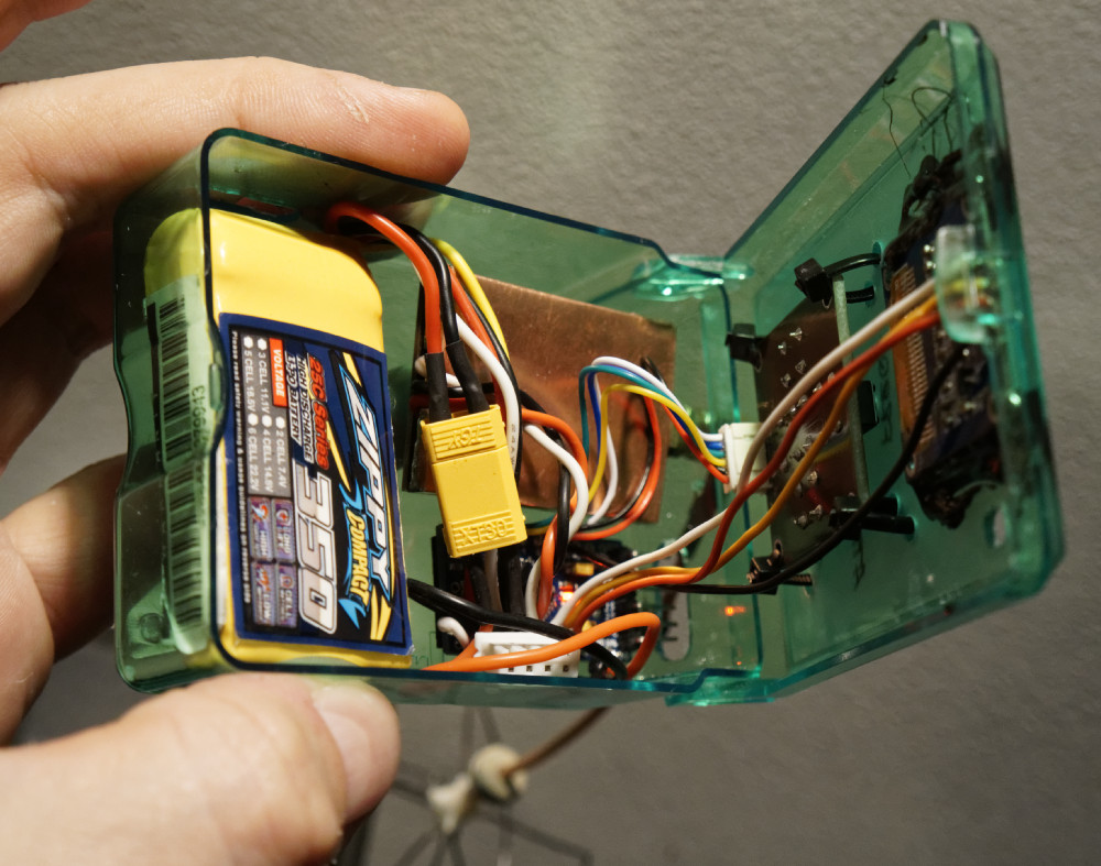
- battery, wires, copper (or alu if you can solder it) foil and other random parts.
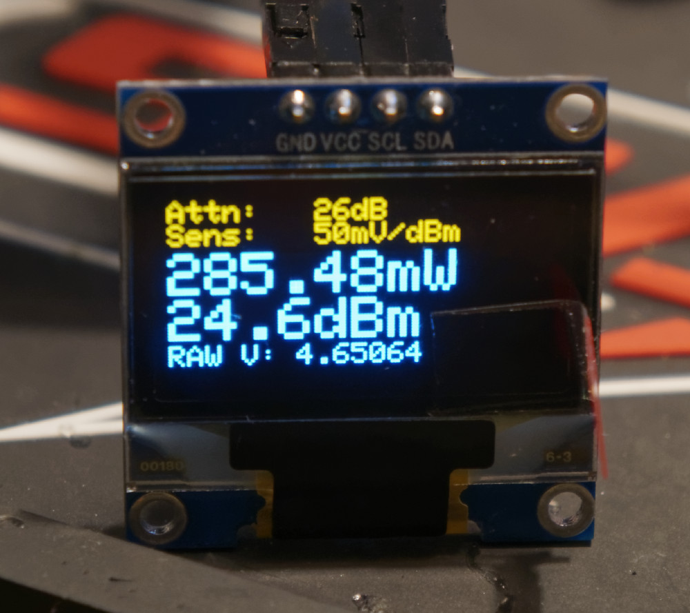
It’s very simple – in fact, it’s just voltmeter with some adjustments. Select attenuator, select frequency, read power in mW or dBm (or raw voltage from chip).
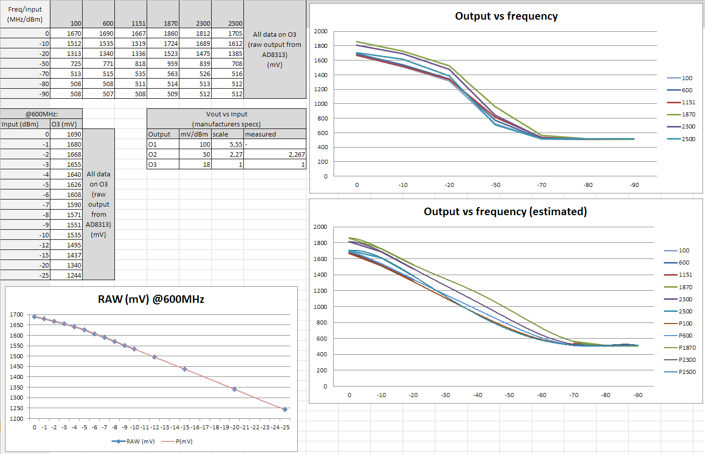
Laidukas provided calibration data for AD8313 (but it’s pretty much follows datasheet, so you may skip this part if you do not want to get max from this chip (you can’t due to <censored> arduino ADC anyway)). Looks good (i interpolated missing points, check notes):
For measuring TX power you need attenuators (max input should be around 0dBm (1mW)) or below (-3dBm if you want accuracy). Put attenuator on, select frequency and attenuator size with buttons, done:
If you want – you can also compare antennas (or measure radiation pattern (ok ok i know – it won’t be accurate blah blah blah, but i’m not flying in ideal conditions). For example – CL with ~1.2dBi (~5m from VTX, 2.4G 500mW with 6dB attenuator on VTX + concrete block between):
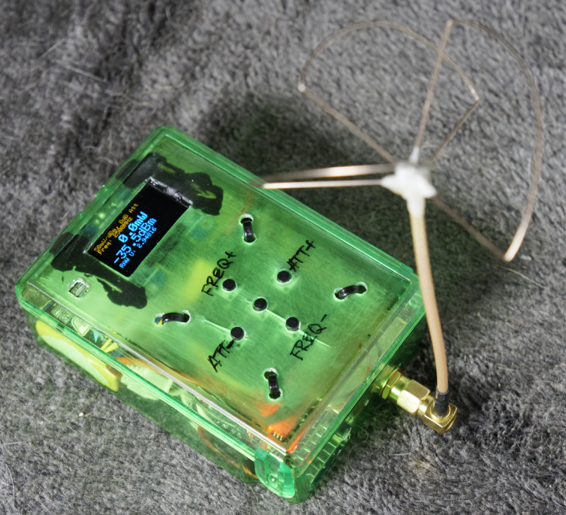
Inclined turnstile 2-element phased array, everything else is the same:
As you can see – there’s 13dBm difference. Real gain is approx 12dB – good enough.
For better accuracy – put RF head into grounded box. For example – make cover from copper foil:
To do (but i won’t continue my work on this, i will get much better ADC and build dual meter, based on ADL5519):
- Paint top of plastic box ;-)
- add battery voltage measurement (i have lots of analog pins and this requires just two resistors and few lines of code)
- move measurement/freq adjustment to -6dB (from 0dB) – better accuracy
- add better ADC (AD7705 or just move to STM32, which has 12-bit ADC instead of 10-bit arduino, better MCU also would allow to use calibration curves for better precision)